
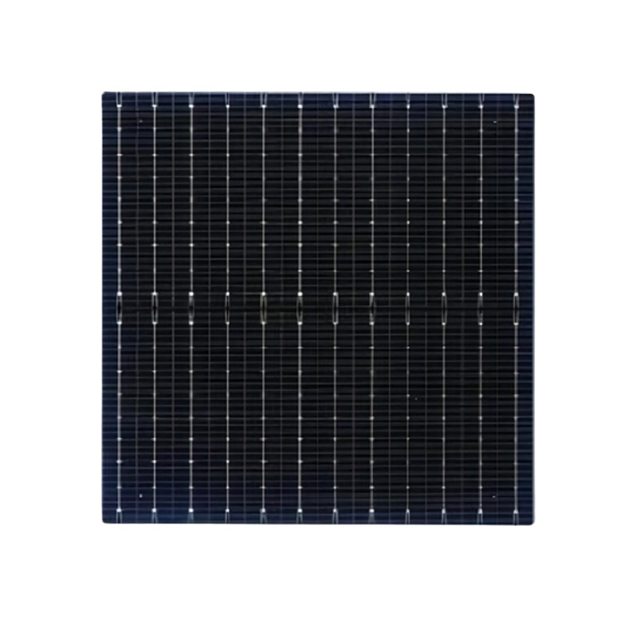
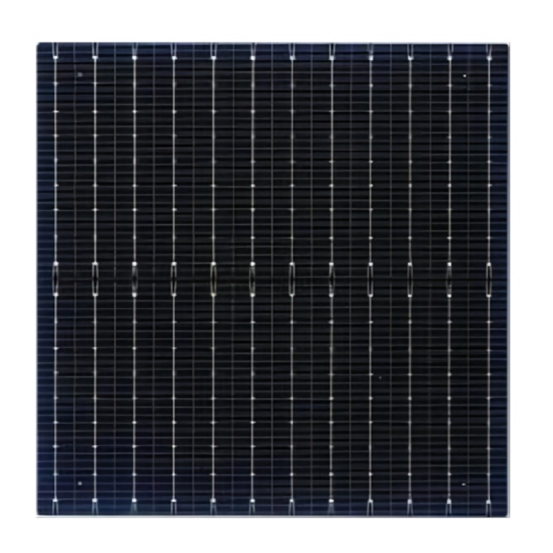
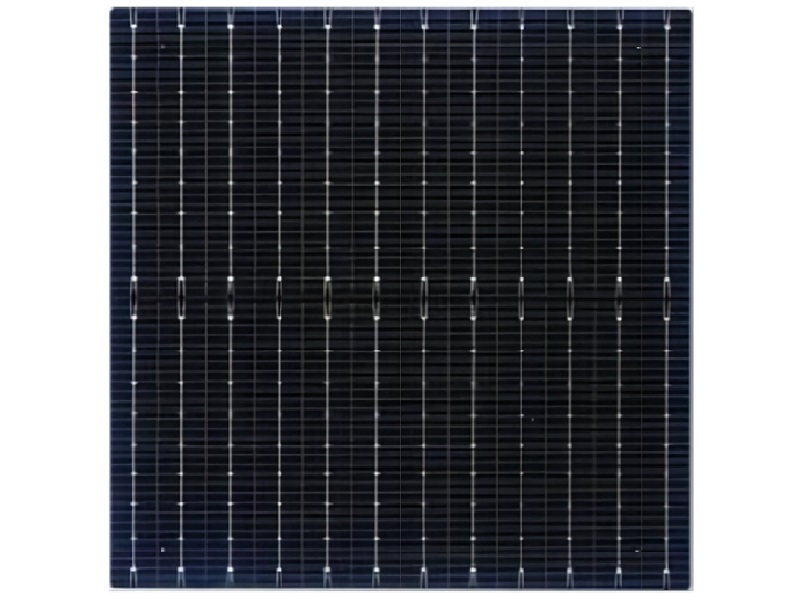
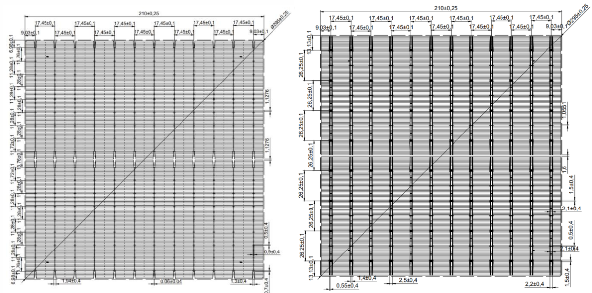
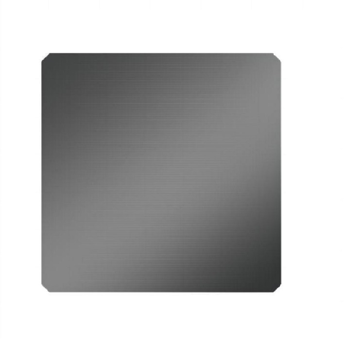
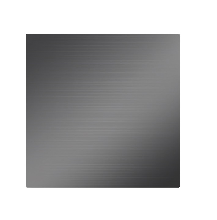
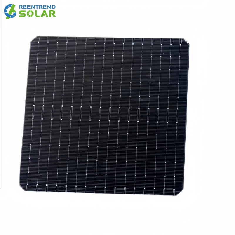
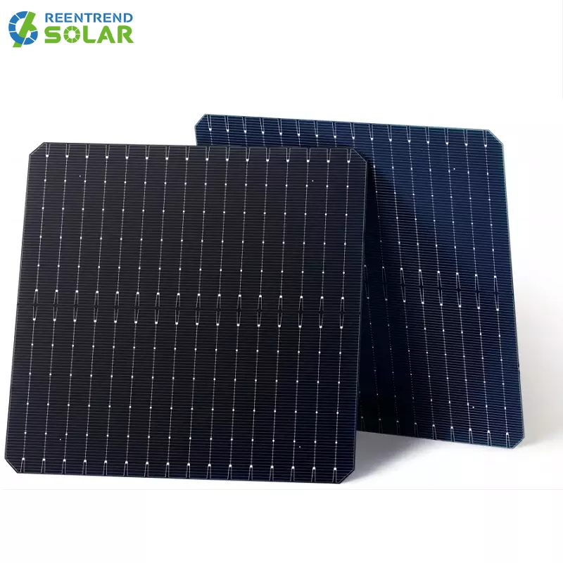
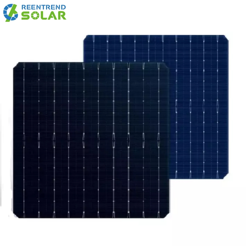
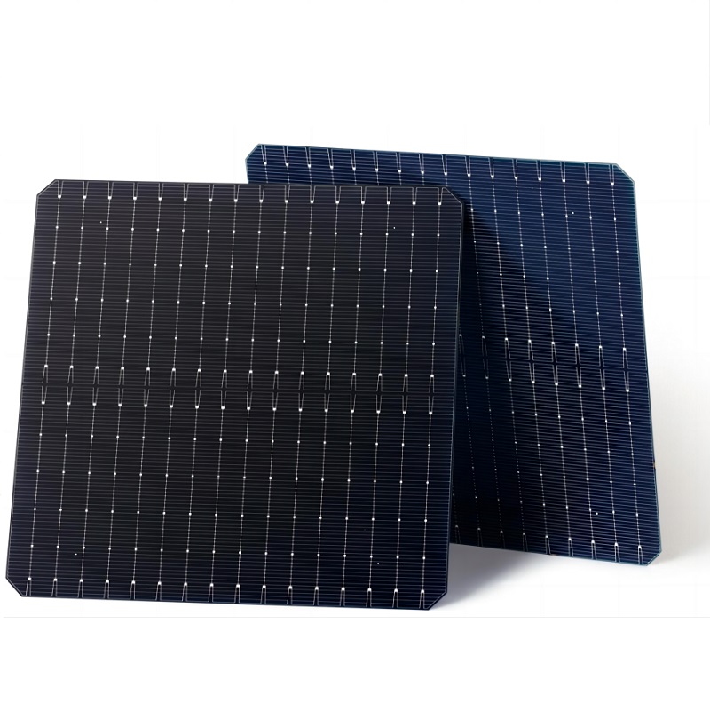
Dimensions :
210mm*210mm±0.25mmThickness :
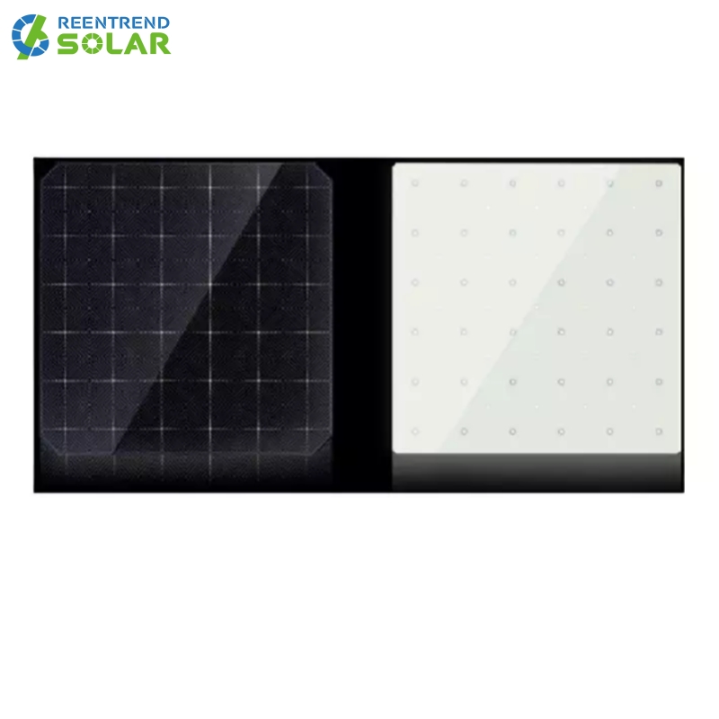
180±20μmFront (-) :
12*0.06±0.04mmbusbar (silver), 174±15 fingers Blue (dark blue)Back (+) :
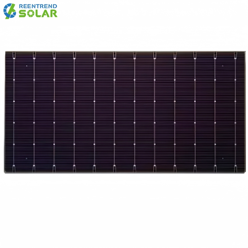
Back electrode width (silver) 2.12 ±0.4mm, back covered with fingers
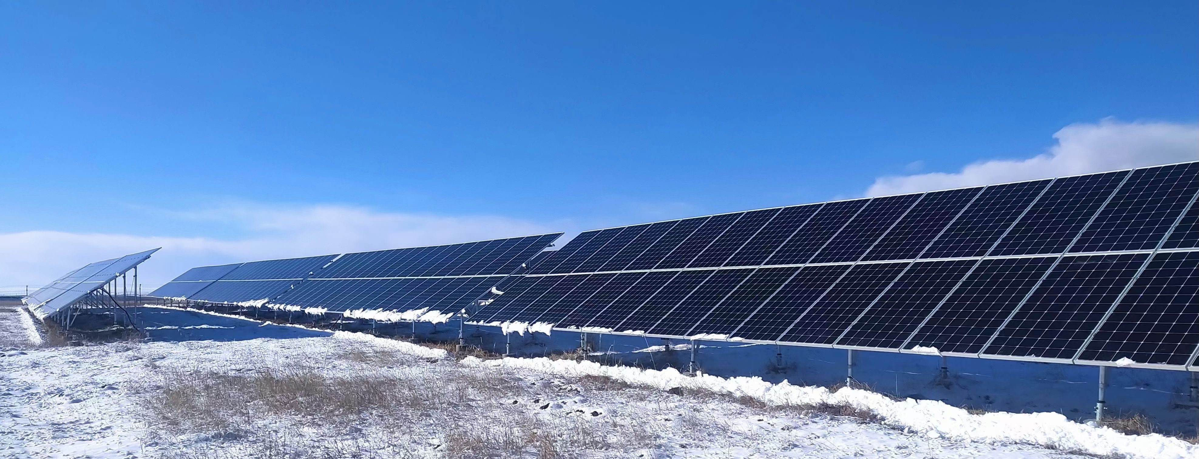
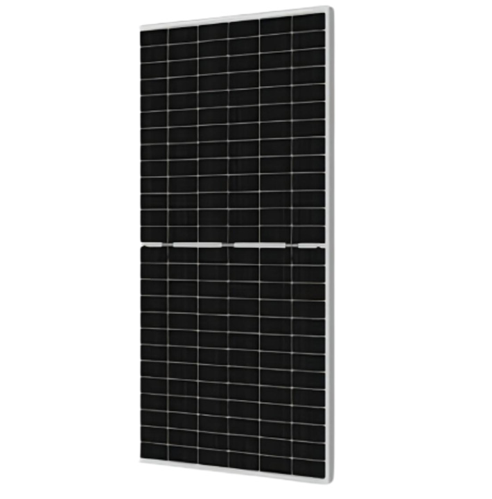
Introduction of PERC Technology
PERC means Passivated Emitter and Rear Contact or Passivated Emitter and Rear Cell .
Traditional cells saw jumps in efficiency when panel manufacturers began putting a front passivation layer to prevent electron recombination at the front panel. Additional bumps in efficiency were achievable by reducing the number of electrons that hit the rear of the panel.
PERC cells take this one step further by placing an additional capping and passivation layer on the rear surface of the photovoltaic (PV) panels, thereby reducing back-side recombination. These layers also help prevent the panels from heating up from unreflected solar radiation. Since panels perform better in cooler temperatures, this helps boost performance as well. PERC cells work in a similar manner but with a few key differences.
The n-type sheet, which is negatively charged, typically contains more atoms that have an additional electron in their outer shell — like phosphorus — to maintain that negative charge.
The positive p-type sheet contains positively charged holes into which those additional electrons can fit. These are usually boron or gallium, which lack one valence electron needed to bond with the silicon around it.
The atoms missing an outer electron — the holes — naturally bond with the atoms that have an extra valence electron. This leaves one additional electron out of the bond, which then gets discharged and collected as electricity.
When solar energy enters the panel, the positive and negative silicon layers naturally rebalance, and the process begins again. While the underlying idea is the same, PERC cells have a few additional layers to prevent the loss of electrons to the outside world.
Engineering Drawing (mm )
Light intensity reliability
|
Intensity(W/m²) |
1000 |
900 |
800 |
600 |
400 |
|
Uoc |
1.0 | 0.996 | 0.991 | 0.988 | 0.962 |
|
Isc |
1.0 | 0.903 | 0.803 | 0.602 | 0.403 |
| * Taking the Voc(Isc) tested at 1000W/m² as the standard, test the decrease of Voc (Isc) with the light intensity. | |||||
Solderability IV curve
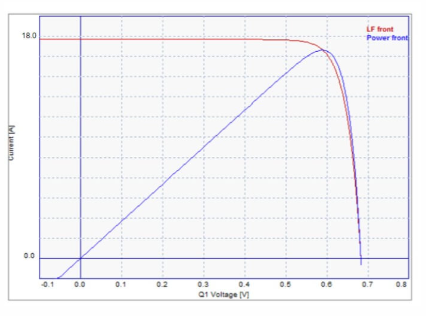
| Minimum peeling strength | ≥1.1N/mm |
| Results may vary depending on electrode, welding method, and conditions. | |
Front Electrical performance distribution
|
Efficiency
Eff(%)
|
Maximum
output power
Pmpp(W)
|
Maximum output voltage Umpp(V) |
Maximumpower
point current
Impp(A)
|
Open-circuit voltage Uoc(V) |
Short-
circuit
current
Isc(A)
|
FF(%)
|
| 23.1 | 10.18 | 9.75 | 17.261 | 0.690 | 18.186 | 81.15 |
| 23.0 | 10.14 | 0.589 | 17.216 | 0.689 | 18.166 | 81.01 |
| 22.9 | 10.10 | 0.587 | 17.206 | 0.688 | 18.140 | 80.93 |
| 22.8 | 10.05 | 0.586 | 17.151 | 0.687 | 18.125 | 80.71 |
| 22.7 | 10.01 | 0.584 | 17.140 | 0.686 | 18.108 | 80.58 |
| 22.6 | 9.97 | 0.583 | 17.101 | 0.685 | 18.088 | 80.46 |
| 22.5 | 9.92 | 0.581 | 17.074 | 0.685 | 18.062 | 80.18 |
| 22.4 | 9.88 | 0.579 | 17.064 | 0.684 | 18.049 | 80.02 |
| 22.3 | 9.83 | 0.577 | 17.036 | 0.682 | 18.030 | 79.94 |
| 22.2 | 9.79 | 0.575 | 17.026 | 0.681 | 18.016 | 79.79 |
| 22.1 | 9.75 | 0.574 | 16.986 | 0.680 | 17.995 | 79.68 |
|
Standard test conditions:1000W/m², AM1.5, 25℃. The above technical parameters are subject to technical changes and tests.
All data contained in this datasheet is subject to change without notice.
|
||||||
Back Electrical performance distribution
|
Efficiency
Eff(%)
|
Maximum
output power
Pmpp(W)
|
Maximum output voltage Umpp(V) |
Maximumpower
point current
Impp(A)
|
Open-circuit
voltage
Voc(V)
|
Short-
circuit
current
Isc(A)
|
| >16 | 7.06 | 0.582 | 12.130 | 0.677 | 13.361 |
| 15.5-16 | 6.92 | 0.579 | 11.952 | 0.675 | 13.352 |
| >15-15.5 | 6.70 | 0.572 | 11.713 | 0.673 | 13.244 |
| <15 | 6.53 | 0.565 | 11.558 | 0.672 | 13.124 |
|
Standard test conditions:1000W/m², AM1.5, 25℃. The above technical parameters are subject to technical changes and tests.
All data contained in this datasheet is subject to change without notice.
|
|||||


 English
 español
 한국의
한국의


 IPv6 network supported