As the demand for renewable energy continues to increase, solar module power generation, as an important energy conversion technology, has been receiving much attention regarding its efficiency and cost. In the field of photovoltaic cell manufacturing, LECO (Laser Enhanced Contact Optimization) technology is gradually emerging.GT Solar's environmentally induced aging solutions provide manufacturers with better support and assurance, playing a key role in product development and quality control. This article will introduce the reliability and durability of photovoltaic modules prepared by LECO-processed photovoltaic cells.

Stability testing of LECO treated module
The LECO process can improve the conversion efficiency of PERC and TOPCon cells. When comparing photovoltaic modules made from LECO-treated cells with untreated cells, the two did not show any difference in accelerated aging and decay tests. The same conclusion was found in tests that far exceeded the thermal cycle and damp heat and humidity freeze tests required by IEC.
Extensive data collected through year-long indoor and outdoor extended accelerated aging tests to verify the stability of LECO-treated PV modules. The test methods for the reliability and durability of photovoltaic modules are:
- Extended Thermal Cycle Test (TC) > 600 times;
- Damp heat test (DH) > 2000 hours;
- Combined stress testing including damp heat test, UV aging, thermal cycle, and high-frequency humidity and freezing test.
Thermal cycle test
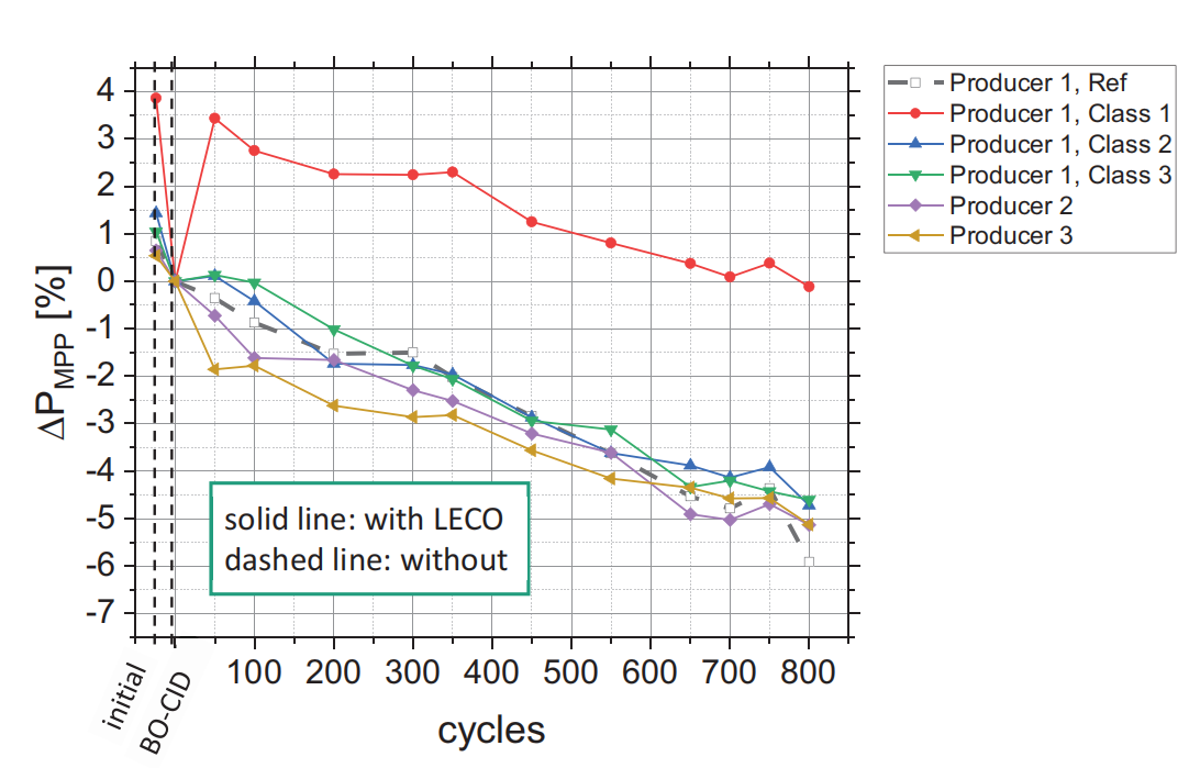
Thermal cycle test results show that photovoltaic modules treated with LECO have comparable stability to those without treatment. Module1 showed severe degradation in the initial BO-CID test (pictured below), but performance gradually recovered over the first 50 cycles due to current injection.

STC power attenuation diagram of LECO-treated components in extended thermal cycle test
All test modules have similar degradation trends: after the standard 200 cycles, the degradation trend is between 1% and 2.5%, which is within a reasonable range. After an extended 800 cycles (4x IEC) there was no deviation from the untreated module and the power drop was at a good 4-6% relative to the test duration.
Damp heat test
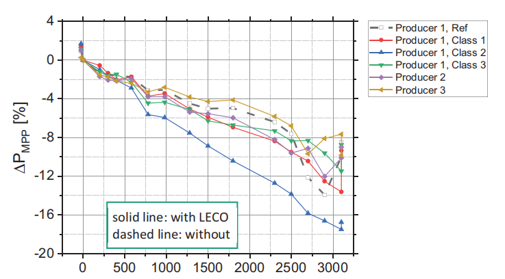
After 1000 hours of extended damp heat testing, the performance of the test modules dropped by 3% to 4.5%, except for module 2 which showed a 6% power loss (pictured below), but since that example showed higher initial degradation, it is likely that part of the degradation can be restored by light immersion or dark current injection. After 3,000 hours of damp heat testing, the attenuation is mostly between 8% and 10%.

STC power attenuation diagram of LECO-treated modules during extended damp heat test
The EL image (as shown below) shows that leakage occurred near the gate line after 2300 hours, and corrosion caused a decrease in short-circuit current and a decrease in fill factor (FF).

Partial EL imaging in extended damp heat test
Humidity Freeze Test
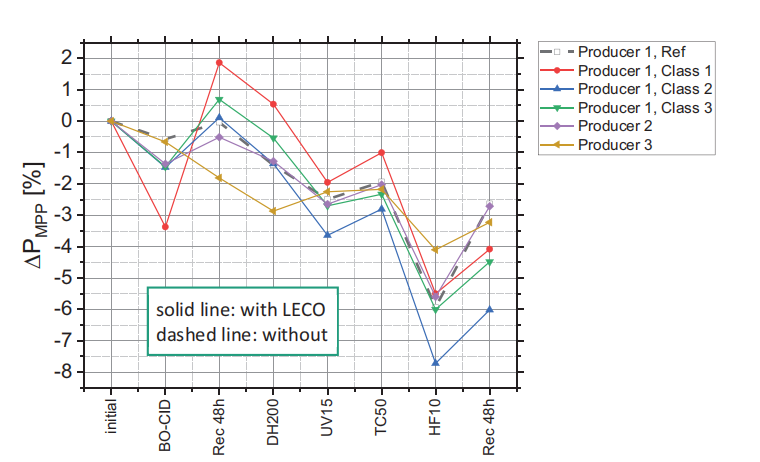
The rapid recovery of module power during the continuity test further proves that it is likely a BO-CID defect. In the test in the picture below, test modules 1 and 4 show almost the same behavior, but there is a relatively large drop in the 10 sets of humidity freeze test, and module 5 is slightly different. The regeneration step in 10 sets of wet-freezing tests showed significant performance recovery for all samples.

STC power attenuation diagram of LECO-treated modules during extended damp heat test
The power loss of most test modules after recovery is between 2.5% and 4.5%, which is comparable to the results of other test modules. The IV curve shows that the power reduction after the Humidity Freeze Test is caused by the reduction of short-circuit current and open-circuit voltage, which can be partially regenerated by the recovery step.
The results of the temperature cycle test show that there is no significant difference between the LECO-treated module and the untreated module in the long-term damp heat and continuity test, but there are significant performance changes. The root cause is the change in open circuit voltage and short circuit voltage.