
How to convert solar cell area/efficiency?
Monocrystalline silicon wafer area
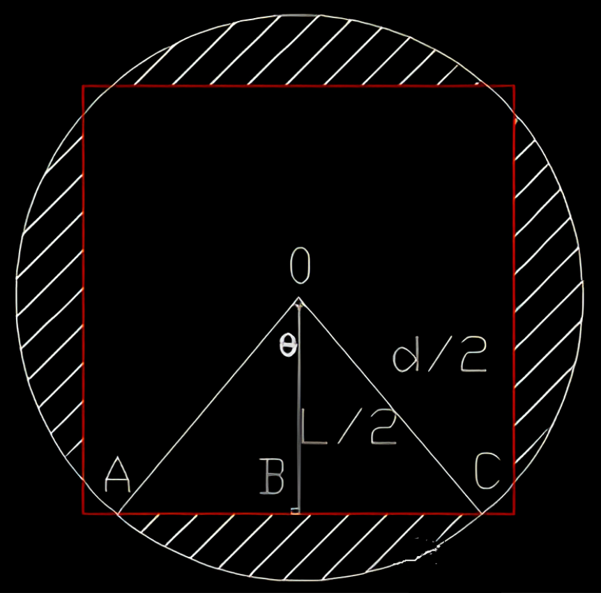
The shape of the single crystal solar cell is generated by cutting a cylindrical silicon rod formed using the cinetol method. The calculation idea of the area of the monocrystalline silicon wafer is derived from the original circular area of the silicon wafer minus the area of the four-sided arc (the area of the silicon wafer is cut and removed during processing, that is, the shadow part in the legend). The calculation process is as follows.
1. Parameter setting.
(1) The diameter of the circular silicon wafer is set as d, that is, the diagonal length of the silicon wafer after cutting;
(2) After the silicon wafer is cut, the diametral length is L, that is, if M156*156 silicon wafer, L=156.
(3) The curved area where one side of the silicon wafer is cut off is S1, the corresponding sector area where the curved side of the silicon wafer is cut off is S2, and the isosceles triangle area inside the sector composed of two radii of the silicon wafer is S3.
2. Formula calculation.
S=π* (d/2) 2-4* S1
=π* (d/2) 2-4*(S2-S3)
= π*(d/2) 2-4 *{(n*π*(d/2)2/360-(2*)*(L/2)/2}
Among them,
S, is the area of monocrystalline silicon wafer, suitable for single crystal arbitrary diametral silicon wafer.
S1= S2- S3;
S2= n*π*R2/360, where n is the central Angle corresponding to the arc length n=2*arcos(L/d), R= (d/2);
S3=(2*)*(L/2)/2; (Area of isosceles triangle OAC S3=AC*OB/2)
3. Efficiency conversion
Uoc (or Voc) : open circuit voltage
Isc: short circuit current
Eat: Efficiency
Rs: Series resistance (also known as internal resistance)
Rsh: Parallel resistance
FF: fill factor
Pmpp: Maximum power
Umpp: maximum power point voltage
Impp: Maximum power point current
Irev1: Reverse current 1(-10V)
Irev2: Reverse current 2(-12V)
Ncell: Conversion efficiency
Unit of light intensity: W/m²
Among all parameters, only voltage and current are measured values, and other parameters are calculated values.
Pmpp is to find a point on the I-V curve, so that the voltage of the point is multiplied by the current to obtain the maximum, the voltage corresponding to the point is the maximum power point voltage Umpp, the current of the point is the maximum power point current Impp
Rs is the ratio of the voltage difference to the current difference at the maximum power point under the light intensity of 1000W/m² and 500W/m², and it is only a calculated value, so sometimes negative values will appear. Many companies use less than 0.0035Ω as the card control standard, if more than 0.0035Ω will be stuck out, because the single string resistance is high, affecting the current of other batteries in the entire component, thereby reducing the power of the entire component.
Rsh is the slope of the dark current curve when the current is close to 0.
Irev1 is the reverse current when the voltage is -10V;
Irev2 is the reverse current when the voltage is -12V.
Rs and Rsh determine FF, and Rsh has a corresponding relationship with Irev1 and Irev2. The calculation formula is as follows:
Ncell= Pmpp/S (wafer area) * Light intensity
Pmpp= Umpp*Impp= Uoc*Isc*FF
FF= (Umpp*Impp)/(Uoc*Isc)
ETA=((Uoc*Isc)* (Umpp*Impp)/ (Uoc*Isc))/W*S (wafer area)
The normal test temperature is 25±2℃. With the increase of temperature, the open circuit voltage decreases sharply, the short circuit current increases slightly, and the overall conversion efficiency decreases.
The normal light intensity is 1000±50W/m², and with the reduction of light intensity, the open circuit voltage is slightly reduced, the short circuit current is sharply decreased, and the overall conversion efficiency is reduced.
Test sorting parameters:
1, open circuit voltage:
Under certain temperature and irradiance conditions, the end voltage of the solar cell under no-load condition is expressed by Voc, and the PN junction is open, that is, I=0, and the voltage at both ends of the PN junction is the open voltage. Substituting I=0 into the voltammetry characteristic equation gives: KTln(IL/IS+1)/q. The open circuit voltage of a solar cell is independent of the size of the cell area. The open circuit voltage of a solar cell is proportional to the logarithm of the incident spectral irradiance.
2, short circuit current:
Under certain temperature and irradiation conditions, the output current of a solar cell when the terminal voltage is zero, usually expressed by Isc. Short-circuit the PN junction (V=0), so IF=0, then the resulting current is the short-circuit current Isc, obviously: Isc= IL, Isc is related to the size of the solar cell area, the larger the area, the larger the Isc. Isc is proportional to the irradiance of the incident light.
3. Maximum power point:
The point corresponding to the maximum power on the volt-ampere characteristic curve of the solar cell is also called the best working point.
4, the best working voltage:
The voltage corresponding to the maximum power point on the volt-ampere characteristic curve of a solar cell. It is usually represented by Vm
5, the best working current:
The current corresponding to the maximum power point on the volt-ampere characteristic curve of a solar cell. It is usually denoted by Im
6. Conversion efficiency:
The percentage of the maximum power of the illuminated solar cell to the total radiated power incident on the solar cell. η= Vm Im/At Pin where Vm and Im are the voltage and current of the maximum output power point respectively, At is the total area of the solar cell, and Pin is the power of the incident solar light per unit area.
7. Filling factor:
The ratio of the maximum power of a solar cell to the product of the open circuit voltage and short circuit current is usually expressed by FF: FF = ImVm/ IscVoc
IscVoc is the limit output power of solar cells, ImVm is the maximum output power of solar cells, and the filling factor is an important parameter to characterize the performance of solar cells.
8, current temperature coefficient:
Under the specified test conditions, every change of 1℃ in the temperature of the measured solar cell, the change value of the short-circuit current of the solar cell is usually expressed by α. For general crystalline silicon cells α= + 0.1%/℃.
9, voltage temperature coefficient:
Under the specified test conditions, the change value of the open circuit voltage of the solar cell is usually expressed by β for every change of 1℃ in the temperature of the solar cell being measured. For the general crystalline silicon cell β = -0.38% /℃.


 English
 español
 한국의
한국의


 IPv6 network supported